Posts

Showing posts from September, 2017

ARM Instruction Set(Part 2): Types,Operands and Addressing Modes

Image
Types,Operands and  Addressing Modes After a brief  introduction of ISA, here in this part of the series we'll look at: Content:   Types of Operands  Instruction set design Types of Instructions Types of Addressing modes Types of Operands: Operands basically refer to the type of parameter which is passed on to, along with an instruction. It might be a : Register/Memory address Constant/Immediate Consider the following examples: ADD r1,r2,r3;      will add r2 and r3 and store it's value in r1 Here, Operands is r1,r2 and r3. ALL of which are registers. ARM has in general 16 general purpose registers out of which last register is Program counter , second last is stack pointer and third last is link register . ADD r1,r2,#3;      will add the value in register r2 and 3 and store it's value in r1 Here, one of the operand is '3' which is a constant. This comes under immediate operands. Some of the instructions even don't have any operand, such type ...
ARM Instruction Set(Part 2): Types,Operands and Addressing Modes

Image
Types,Operands and  Addressing Modes After a brief  introduction of ISA, here in this part of the series we'll look at: Content:  Types of Operands  Instruction set design Types of Instructions Types of Addressing modes Types of Operands: Operands basically refer to the type of parameter which is passed on to, along with an instruction. It might be a : Register/Memory address Constant/Immediate Consider the following examples: ADD r1,r2,r3;      will add r2 and r3 and store it's value in r1 Here, Operands is r1,r2 and r3. ALL of which are registers. ARM has in general 16 general purpose registers out of which last register is Program counter , second last is stack pointer and third last is link register .  ADD r1,r2,#3;      will add the value in register r2 and 3 and store it's value in r1 Here, one of the operand is '3' which is a constant. This comes under immediate operands. Some of the instr...

DIY: Generating Ramp/Sawtooth from PWM

Image
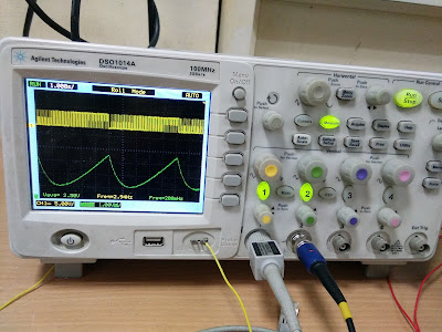
DIY: Generating Ramp/Sawtooth from a PWM signal Lack of any good tutorial to produce a ramp/sawtooth wave from a PWM signal, urged me to make one! This post was in fact a part of one of my recent ongoing project i.e Redesigning the Semiconductor CURVE TRACER,  here at CEDT, NSIT. I was to produce a sawtooth wave from a pwm signal using arduino nano and here are my observations: TASK:  To produce a sawtooth wave from PWM signal using Arduino Nano. PROCEDURE: Producing a ramp/sawtooth wave out of a PWM signal merely involves passing a PWM signal of varing duty cycle through a low pass filter. Here's the code I used : /*Code for prodcing a Sawtooth wave from PWM*/ int pwm_pin = 9;           int brightness = 0;   int upramp(int brightness) {   while(1)   {   brightness+=5;   delay(100);   analogWrite(pwm_pin, brightness);   if(brightness>250)   {   digitalWrite(pwm_pin,LOW); // ...

DIY: Generating Ramp/Sawtooth from PWM

Image
DIY: Generating Ramp/Sawtooth from a PWM signal Lack of any good tutorial to produce a ramp/sawtooth wave from a PWM signal, urged me to make one! This post was in fact a part of one of my recent ongoing project i.e Redesigning the Semiconductor CURVE TRACER,  here at CEDT, NSIT. I was to produce a sawtooth wave from a pwm signal using arduino nano and here are my observations: TASK:  To produce a sawtooth wave from PWM signal using Arduino Nano. PROCEDURE: Producing a ramp/sawtooth wave out of a PWM signal merely involves passing a PWM signal of varing duty cycle through a low pass filter. Here's the code I used : /*Code for prodcing a Sawtooth wave from PWM*/ int pwm_pin = 9;           int brightness = 0;   int upramp(int brightness) {   while(1)   {   brightness+=5;   delay(100);   analogWrite(pwm_pin, brightness);   if(brightness>250) ...